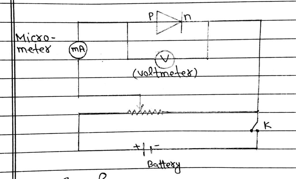
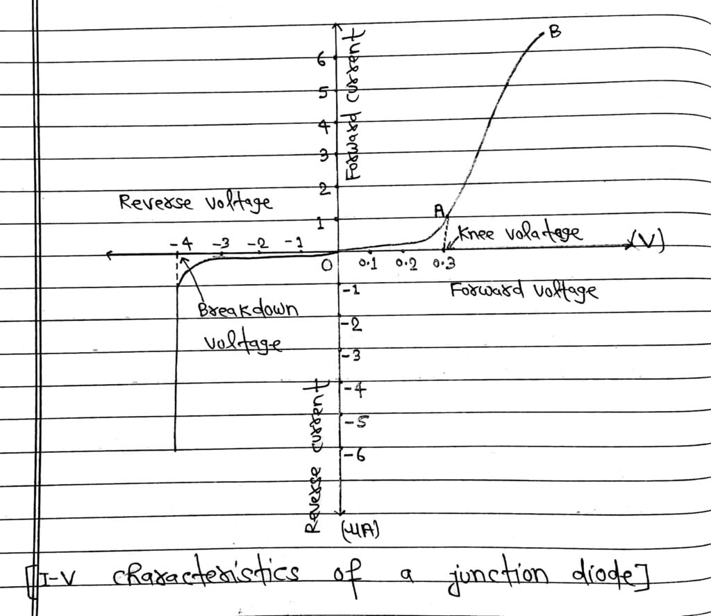
The graphical relation between voltage applied across PN junction and current flowing through the junction are called I-V characteristics of junction diode.
1. Forward Biased Characteristics
From a low value, forward biased voltage is increased step by step (measured by voltmeter) and forward current is noted (by ammeter. A graph is plotted between voltage and current.

From Graph
(I) From graph, V-I curve is not a straight line ie. junction diode does not obey ohm’s law.
(II) At the start when applied voltage is very low, the current through the diode is almost zero, it is because of potential barrier.
(III) Till the applied voltage exceeds the potential barrier, the current increases very slowly with increase in applied voltage (OA portion of the graph shows this).
(IV) With further increase in applied voltage, the current increases very rapidly (AB portion of the graph shows this). In this situation the diode behaves like a conductor.
The forward voltage beyond which the current through the junction starts increasing rapidly with voltage is called Knee voltage.
2. Reverse Biased Characteristics
In Reverse Biased, the applied voltage supports the flow of minority charge careers across the junction. So a very small current flows across the junction due to minority charge careers.

Now, voltage across the junction increased step by step and note down corresponding voltage and current.
When the reverse voltage across the PN junction reaches a sufficient high value, the reverse current suddenly increases to a large value. The value of voltage at this time is called breakdown voltage.
At breakdown voltage, suddenly current increased rapidly and PN junction diode maybe damaged.

Also Read: CBSE Class 12 Physics Chapter-14 (Semiconductor and Electronic Devices) All Topics
