
Special Purpose P-N Junction Diode (Zener Diode)
A Junction diode specially designed to operate only in the reverse breakdown region continuously without getting damaged is called zener diode.
Zener diode with different breakdown voltages can be obtained by changing the doping concentrations of p and n side which in terms change the width of depletion layer and also the barrier field across the junction
Representation of zener diode-

V-I Characteristics Of Zener Diode
From graph we observe that when the applied reverse voltage (V) reaches the breakdown voltage (Vz) of the zener diode, there is a large change in the current.
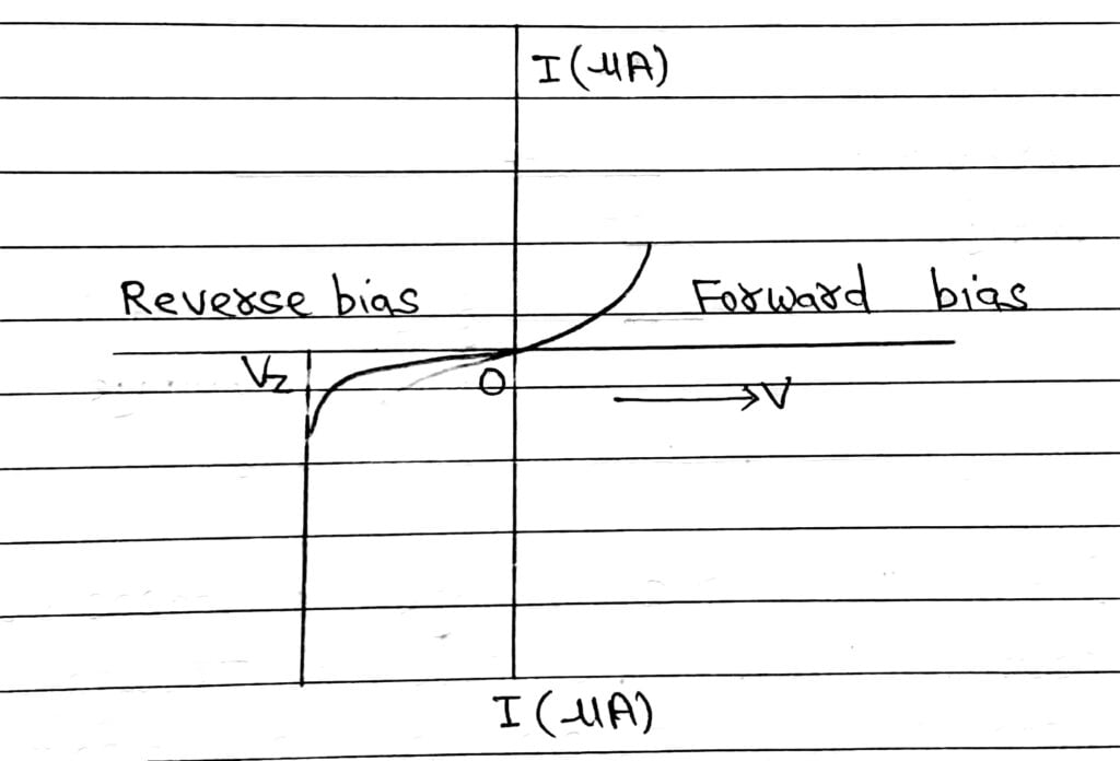
After the breakdown voltage Vz, a large change in current can be produced by almost insignificant change in the reverse bias voltage.
Zener Diode As a Voltage Regulator
Principle
Zener diode is operated in the reverse breakdown reason. The voltage across it remains practically constant and equal to break down voltage Vz for a large change in the reverse current.
Working
From figure the zener diode is connected in Reverse bias to a source of fluctuating DC, through a dropping register Rs.
Thus the voltage gets divided between Rs and zener diode. The output is obtained across the load resistance RL connected in parallel with the Zener Diode.

When input DC voltage increases beyond a certain limit, the current through the circuit rises sharply, causing a sufficient increase in the voltage drop across the register Rs. Thus, voltage across the Zener diode remains constant and also the output remains constant at Vz.
When the input DC voltage decreases, the current through the circuit goes down sharply causing sufficient decrease in the voltage drop across the resistance. Thus the voltage across the Zener diode remains constant and also the output voltage across RL remains constant at Vz.
Hence, output voltage remains constant in both conditions.
The below graph shows output voltage Vo verses input voltage Vin for zener diode. The output voltage remains constant after the reverse breakdown Vz.

Also Read: CBSE Class 12 Physics Chapter-14 (Semiconductor and Electronic Devices) All Topics